

This guide describes the installation of the footwell lights controlled by BCM and CDB (MFA+ white) on my Golf MK6 Plus.
Apart from a few small details this guide can also be used for the Golf MK6 sedan.
It can also be used as a starting point for the Golf MK5, but be careful, in this case changes the control unit and pin-to-wire on it: if you search on the net there are well made several specific guides.
Installation is fairly simple, it takes about 2-3 hours of work, depending on the level of finish you want to achieve and of their level of dexterity.
My installation included the use of LEDs for lighting and taping of all wiring to avoid vibration and to get closer to a wiring harness.
Keep in mind that if you want to use LEDs for illumination must necessarily use those type CANBUS as controlled by CDB.
Obviously it is an electrical / electronic work on the installation must pay the utmost attention and care in performing the work.
Required Materials
VW material
2x footwell light cod. 7L0 947 415 (the ceiling lights are already equipped with 3W bulb)
2x flat connector cod. 1J0 971 972
4x repair wire cod. 000979131
1x repair wire cod. 000979025
1x tape VW cod. 000 979 950
Electrical equipment
4/5 meters 1.5mm power cable (I used brown cable to the negative /GND, blue cable to the positive)
2x faston eyelet (hole Ø = 6 mm, ext Ø = 16 mm)
2x LED CANBUS T10 W5W
Equipment
Welder
Heat shrinkable tube
Ties electrician thin
Torx screwdriver 20
Hex wrench 10mm
Plastics removal tools
VCDS for programming the BCM
job Description
On the Golf MK6 exist only predispositions for footwell lights.
The work consists in realizing the electrical system and encode the control unit of the vehicle electrical system so that drivers these lights.
The first thing to do is identify the predispositions of the overhead lights on the left and right of the dashboard.
In photo predispositions for footwell lights of the Golf MK6 Plus: the left one is a side view of the ODB-II connector, the right one is the base of the glovebox.
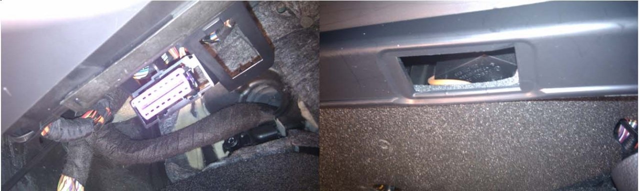
On the Golf MK6 sedan predispositions they are not already finished but only pre-cut. Furthermore, the left one is different.
The circuit diagram is very simple to prepare: in practice the control unit supplies the positive to the two footwell lights. The negative must be taken by the vehicle frame. For convenience I have identified two bolts through the sides of the bridge as easily accessible and close to the ceiling.
Wiring diagram
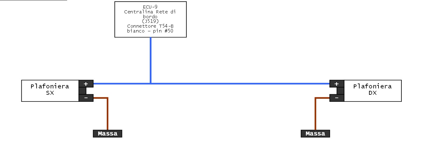
Assembly diagram

The on-board network control unit -J519-
Positioning: Under the driver's side dashboard
Pinout 52-pin connector -T52 B- White B-
01 — Fuse 21 in fuse holder C -SC21-, central locking
02 — Servo wiper -V12-, pump for washing the rear window and windshield -V59-
03 — Free
04 — Free
05 — Free
06 — Free
07 — Free
08 — Free
09 — Free
10 — Free
11 — Servo of the opening device of the rear hatch lock -V139-
12 — power supply relay terminal 15 -J329-
13 — Free
14 — Switch -E16- heating, rear window defroster indicator -K10-
15 — intensity regulator of the instrument lighting and switches -E20-
16 — the sliding roof unit -J245-
17 — the sliding roof unit -J245- Closing comfort
18 — Free
19 — Free
20 — Free
21 — the heating control unit -J774- of the front seats, the seat heating on and off
22 — Relay rear window defroster of -J9-
23 — Free
24 — the hazard warning lights button -E229-, plant indicator flashing -K6-
25 — Free
26 — Free
27 — Free
28 — Relay contact disengagement X -J59-
29 — power supply relay terminal 50 -J682-
30 — intensity regulator of the instrument lighting and switches -E20-
31 — Free
32 — Free
33 — wiper servo motor control unit -J400-, rain and light detection sensor -G397-, LIN bus
34 — Free
35 — Free
36 — -H12- Warning horn, the alarm volumetric sensor -G273-, the vehicle tilt sensor -G384-, LIN bus
37 — deactivation switch -E267- the alarm volume, deactivation of the alarm indicator volumetric -K162-
38 — Fuel supply relay -J643-, the fuel pump control unit -J538-
39 — Free
40 — Relay headlight washer system -J39-
41 — Relay horn duotone -J4-
42 — Fuse 48 in fuse holder C -SC48-
43 — Positive connection 1 (30g) in the beam of the main cables -B559-
44 — Free
45 — Free
46 — Free
47 — Free
48 — Free
49 — Free
50 — Light of left footweel-W9-, light of right footwell-W10- <-must be connect this wire
51 — Connection 1 (58d) in the beam of the main cables -B340-
52 — Earth connection 2 in the beam of the main cables -367-
Installation
I have done the job without removing the battery in the following order:
ceiling assembly
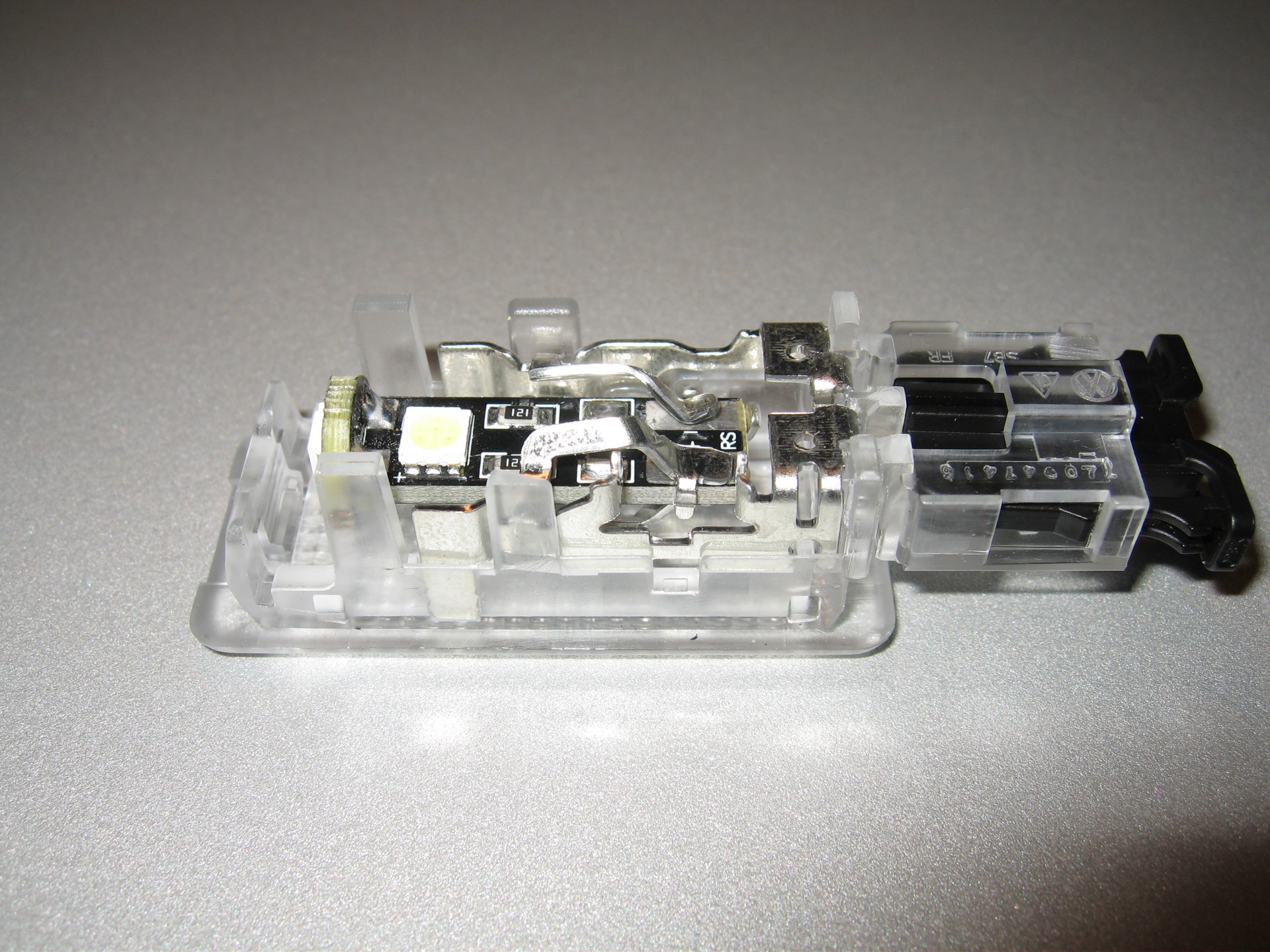
The kits are of normal incandescent bulbs. I I replaced with CANBUS / No Error LED as controlled by the BCM. The light fixtures and related spinet are polarized therefore necessary to verify compliance with the polarity of the LED with a tester.
Removing the left side plank mask
This phase is specific for the Golf MK6 Plus and is required to access the BCM and remove the white connector B. In the figure the dismantling scheme.
For Golf MK6 Sedan simply remove the panel under the steering wheel.

Remove the side cover of the driver's side dashboard
Remove the light switch, according to this procedure:
"0" push forward the switch until it locks
Holding down the switch to turn right into "positions"
We hear a clicking noise. Pulling the switch towards you: the Switch lights slips without resistance.
To reassemble the same reverse order.
Obviously the parking lights remain on. To turn off the lights reposition the switch to "0" and disconnect the connector.
Remove the glove box in the lower left (6)
Remove the cover of the column casing from the bridge (just the left side) according to this procedure:
Adjust the steering wheel all the way down
Take cover at both ends and simultaneously pull down towards you
At this point the cover is lifted just enough to let the screw 2 views
Unscrew the screws holding the mask in this order 1-2-3-4-5-7-8-9
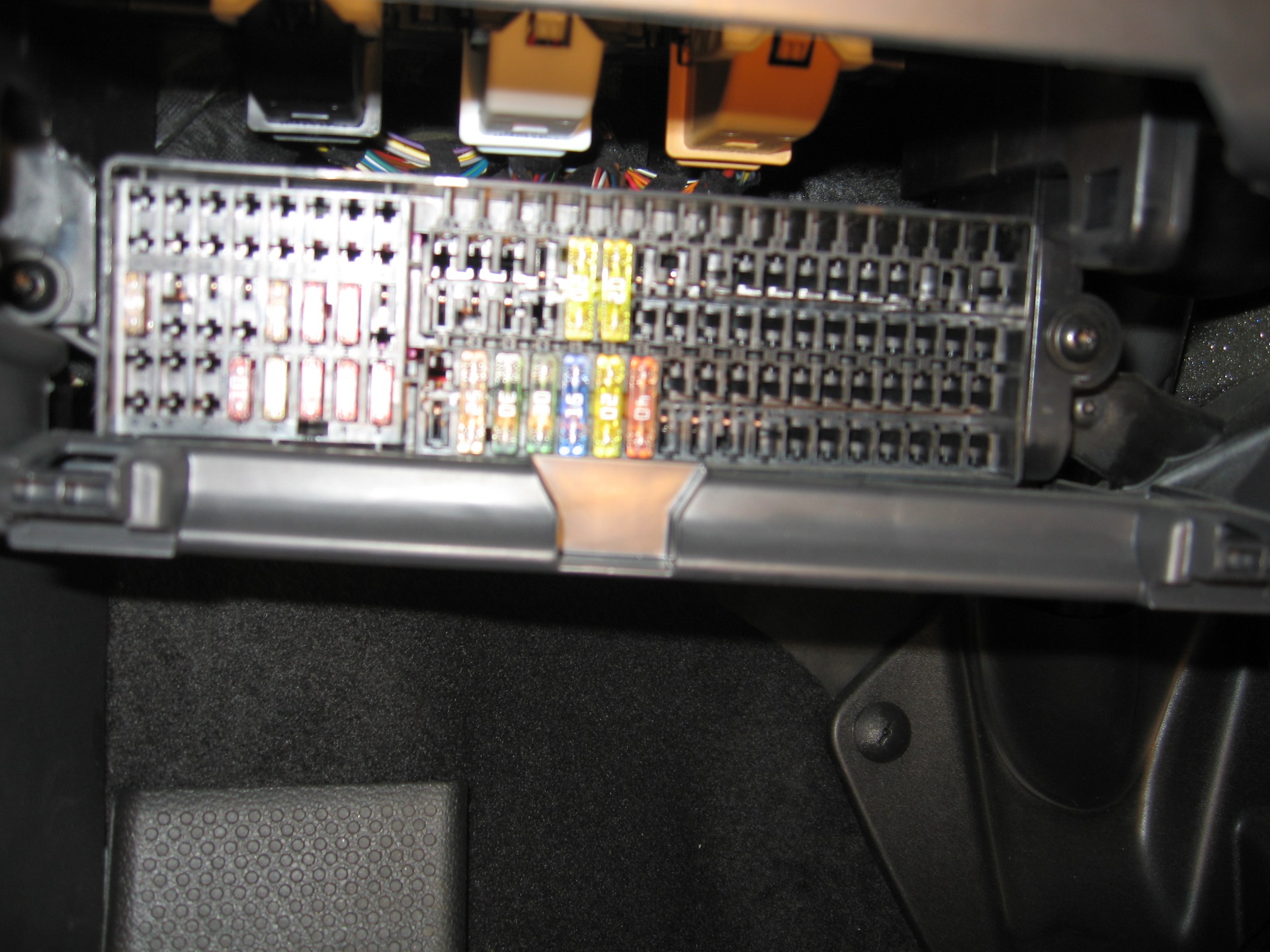
Remove the fuse located under the dashboard by removing the 2 screws to the sides. Behind the fuse unit is the on-board network. In the picture you see the B connector (white)
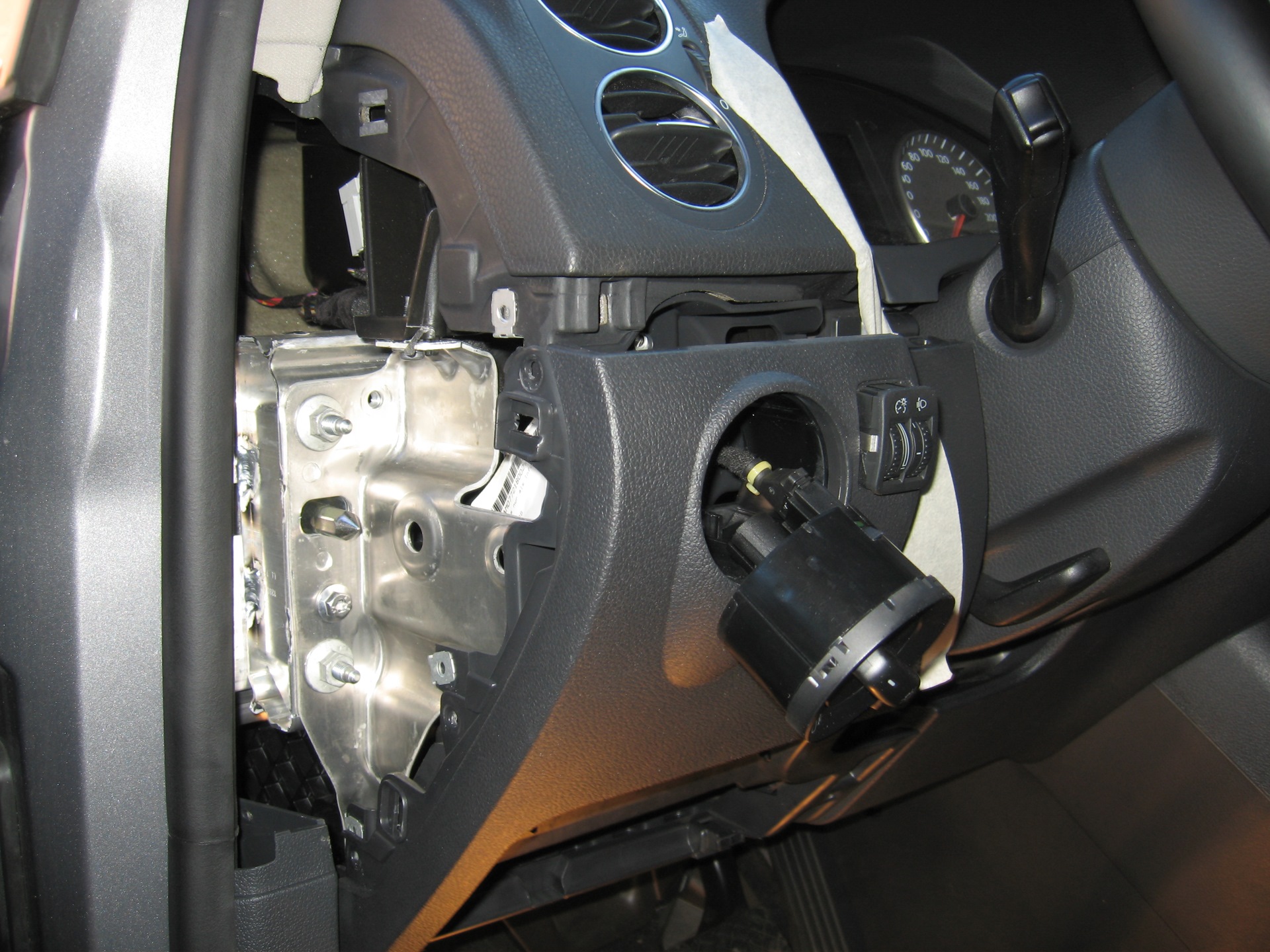
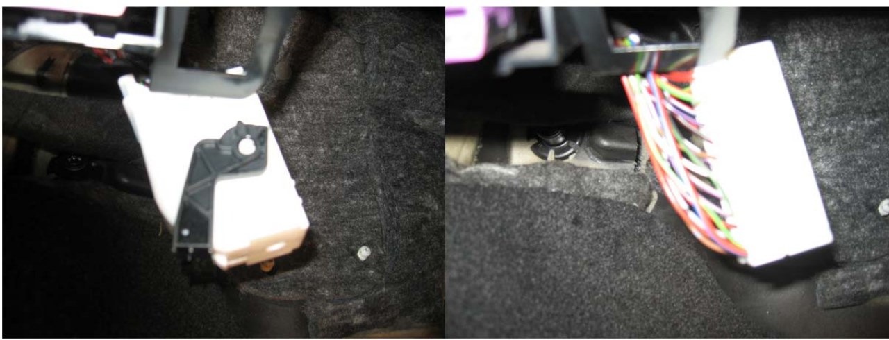
The connector B is removed by releasing the black block: it moves by pressing the white tab on the connector. After removing the connector with the aid of a small screwdriver they release the two tabs to pull the comb contacts from white shell. Now everything is ready for wiring.
wiring assembly to the ceiling
Serving the connector 1J0 971 972 with the repair wire 000 979 131.
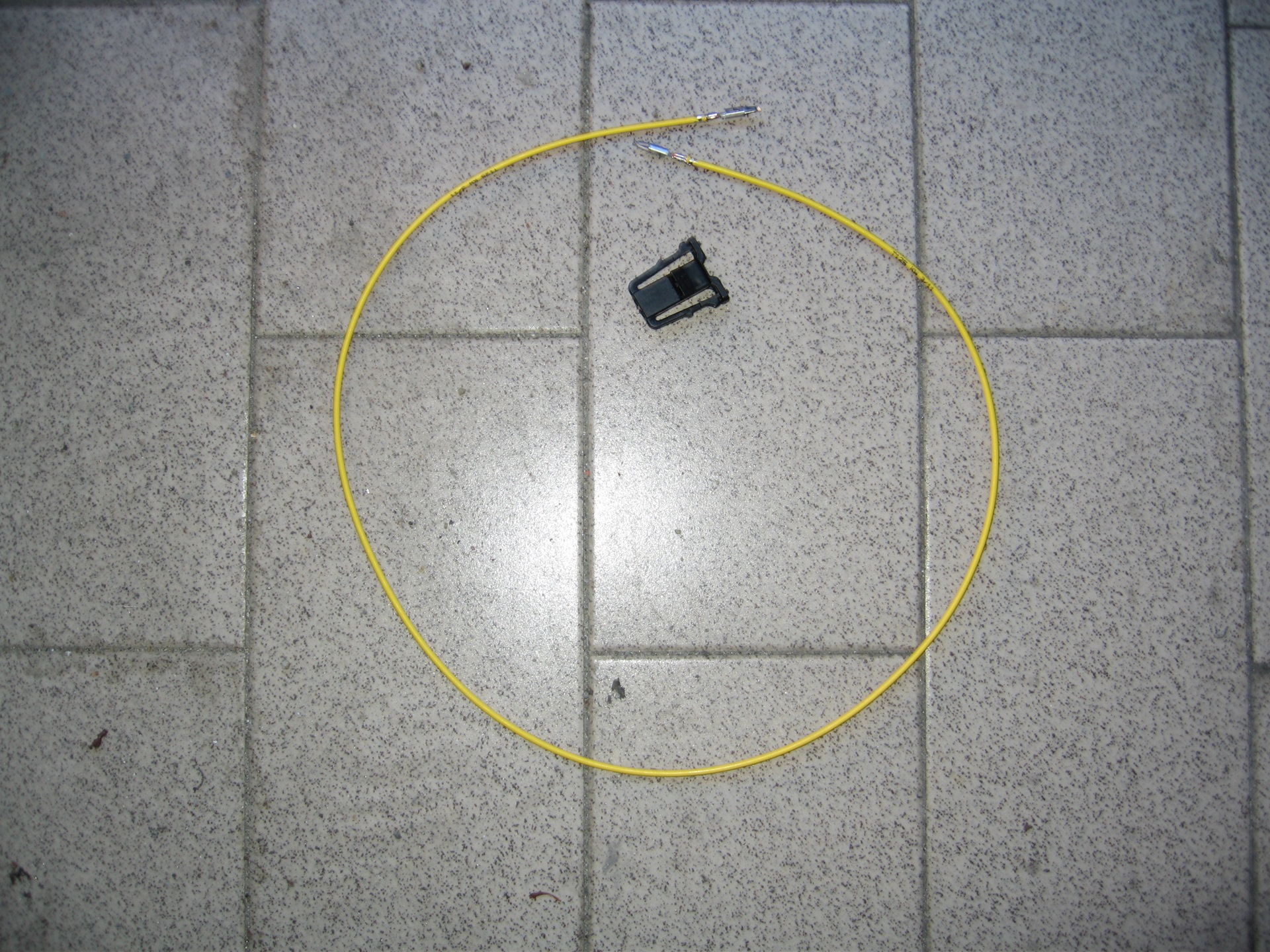
First prepare the wires of the grounding. Take a cable and a spinet. Insert both pins in a spinet. Respect the Convention: Pin1 = negative — pin 2 = positive. Mark the positive (I used a red marker pen).
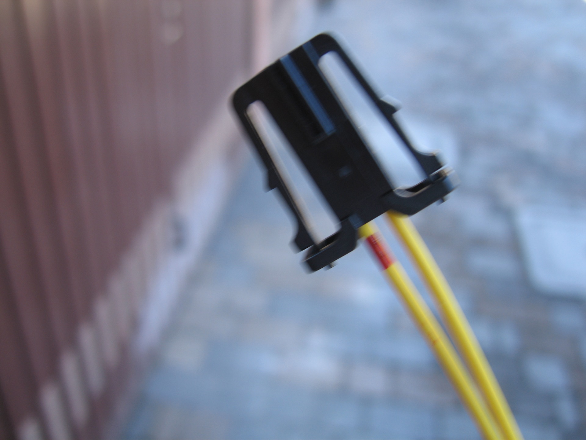
Cut the cable so that you have two pieces of half the length. Strip the free end of 1cm. Take 40/50 cm strip of brown, strip 1cm. Twist, solder and cover with heat shrink tube.
Wire the sockets eyelet for ground connection with brown strap length. To do a good job should be respected these simple rules:
The ground wire should be as short as possible. On Golf MK6 Plus are about 40 cm.
For fastening: stripped cable of length equal to crimp clips for having the greatest amount of contact with the eyelet copper.
Crimp the eyelet, cover with heat shrink tube
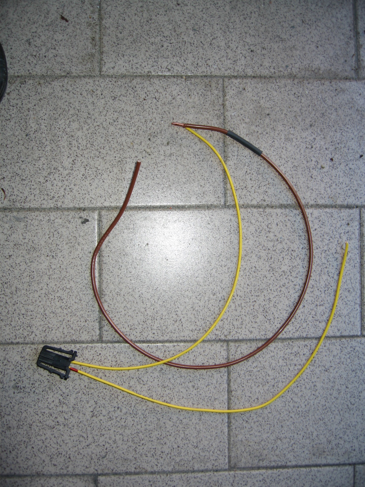
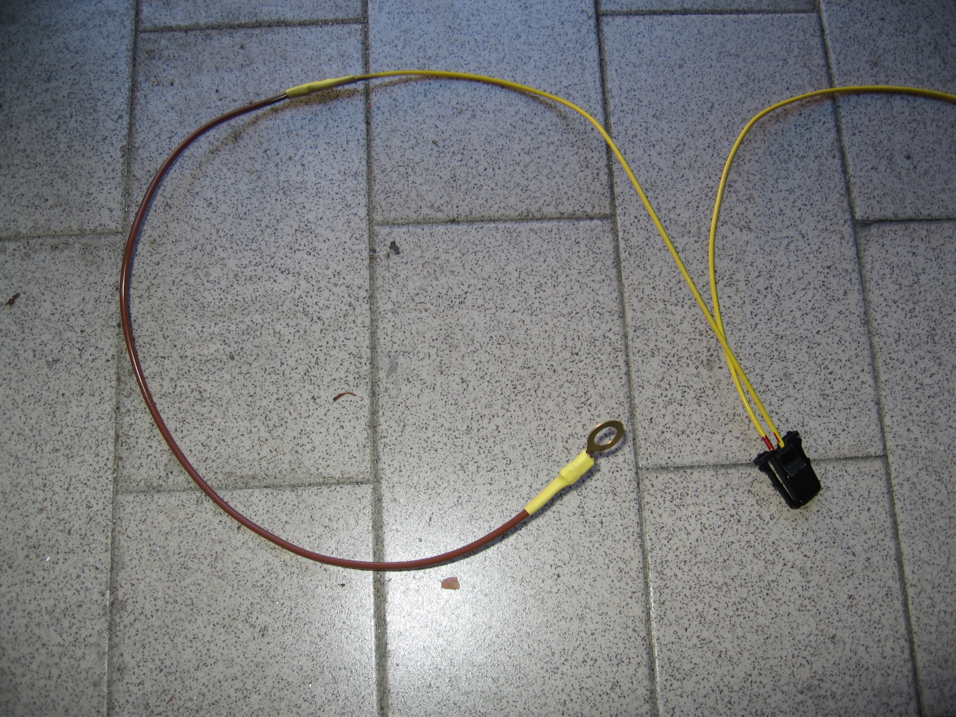
Now assemble the wiring to connect the positive wiring, prepared above, the pin 50 of the connector B.
Take one of the two prepared wiring.
Cut one end of repair wire 000 979 025 and strip approximately 1 cm.
Strip 1 cm the positive lead of the ceiling light.
Strip of 1 cm a length of 2/3 meters of blue ribbon (will serve to bring the positive on the passenger side ceiling).
Twist and solder the ends 3.
Cover with shrink tubing and tape VW.
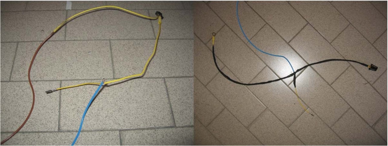
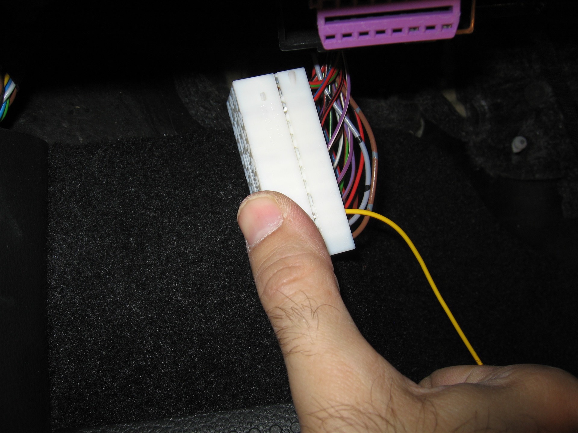
Insert the pin of the repair wire 000 979 025 in the position 50 of the B connector (the locations are embossed on the same connector). Replace the shell.
Attach the eyelet of this harness in the left side by the shortest route to get to the B connector To unscrew / screw the bolt serves a hex wrench 10mm.
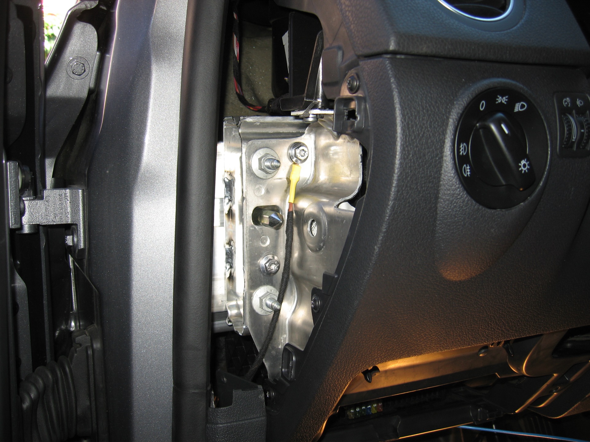
Replace the connector B in the unit Network board and proceed to lock the wiring with cable ties and duct tape VW. Be careful to leave some wire wealth to remove the light easily.
It connects the spinet the ceiling and put it in place. At this point the connection for the left side is completed. The blue wire can be seen is the positive that will lead in the right ceiling.

To bring the positive on the right side of the dashboard is the best step: go behind the steering column, cross the base of the center console, go behind the edge of the passenger side carpet and reach the compartment of the right ceiling. To do this you only need to remove the two bulkheads on either side of the central tunnel and the panel covering the pollen filter (under the glovebox). The cable passes easily with the help of a sensor cable guides.
To avoid vibrations I proceeded to cover the cable with the usual duct tape VW.
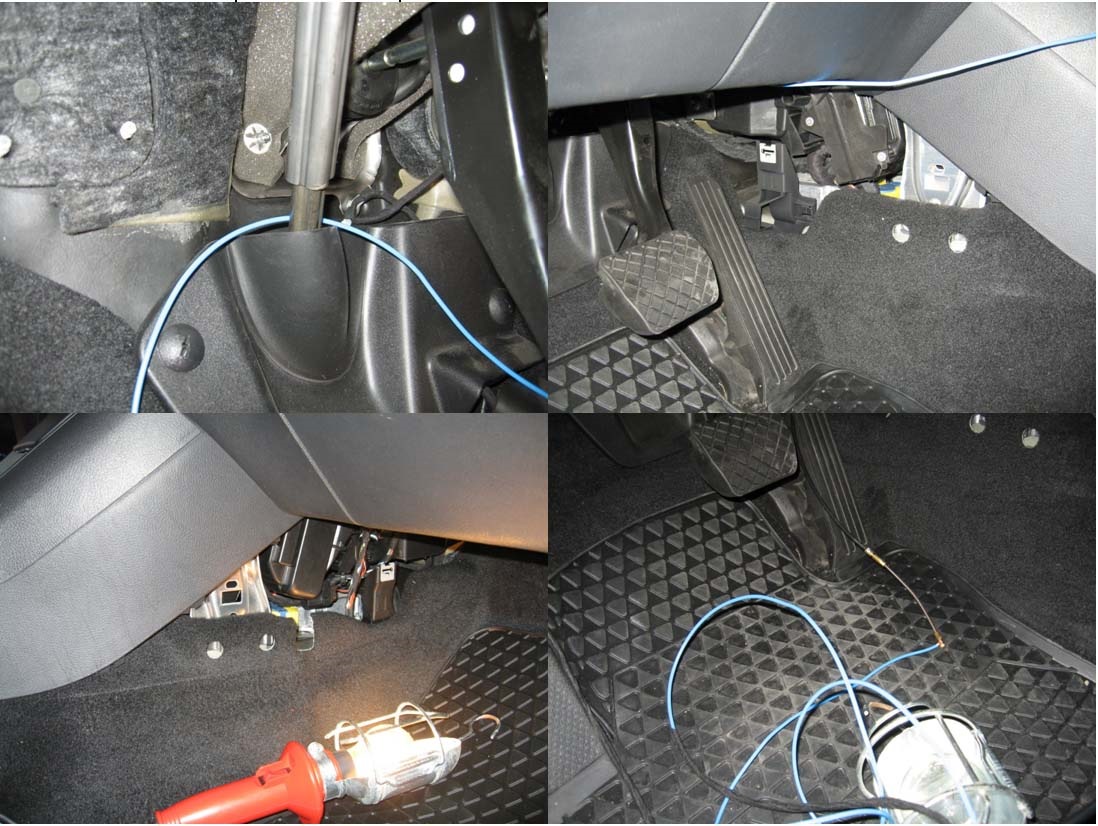
Cut the positive cable of a sufficient length to comfortably remove the light and you switch to weld the positive of the second wiring. VW is covered with duct tape to prevent vibrations.
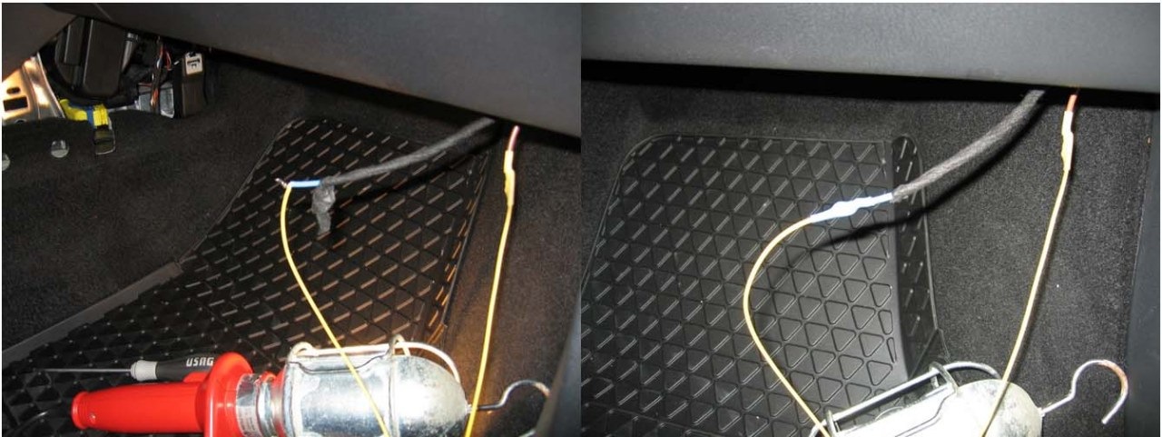
Attach the eyelet of this harness in the right side of the dashboard by the shortest route to get to the right of the ceiling light fixture. Taped with duct tape VW. Insert the lamp into place.

Now you can fix the cables so they do not interfere with the steering column and do not vibrate using electrician's ties and duct tape VW.
Replacing the left side plank mask
This phase is specific for the Golf MK6 Plus. For the Golf MK6 sedan simply replace the panel under the steering wheel.
Replace the fuse holder.
Reassemble the mask tightening the screws in the order: 3-7-5-4-2-1-9-8.
Reinstall the glovebox.
Replace the switch lights.
Coding
After installation of the electrical wiring you can move on to encoding via VCDS.
In practice it must be enabled in the control of these lights by BCM opening / closing doors and slipping off the ignition key.
If the car is equipped with CDB Plus (MFA + white) will appear under the heading LIGHTING a menu that will allow you to enable / disable the function and to vary the light intensity (see photo).
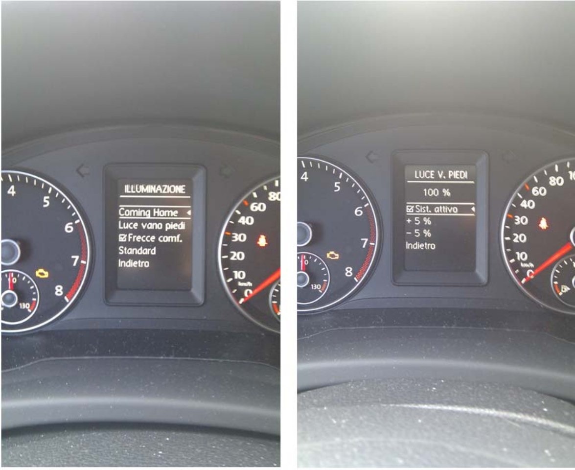
The encoded string is: Module-09> 07-coding> byte20> bit0 = ON
By saving the string the lights come on immediately good response of the work done!
If you have not disconnected the battery while the work is strongly advisable to make an All DTC reset as pulling the plug hot B appear several errors on Module-09 (BCM).
There is another program that allows you to enable the dimming of the footwell lights while driving. In my case the BCM (2009) to activate when I turn on the positions but adjusts the highlights only at 100% intensity.
Will not let me change the intensity in the CDB or via VCDS. On newer versions of BCM (I assume since 2010) that it is possible.
The encoded string is: Module-09> 07-coding> byte12 > bit5 = ON
Enjoy!
Comments 3
Че за нах?))
Very nice and detailed report! Good job.
well done, I too did everything.